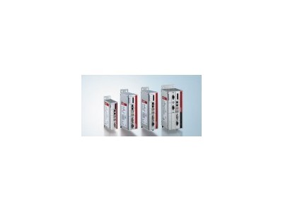
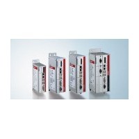
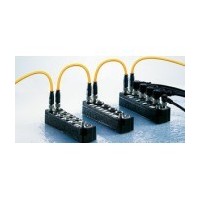
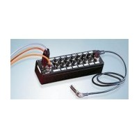
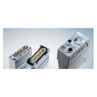
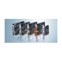
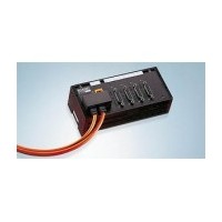
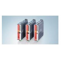
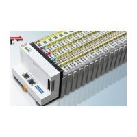
The BK3000, BK3010 and BK3100 and BK3110 bus couplers are used to connect PROFIBUS systems with electronic terminal blocks that can be extended in a modular manner. Each node consists of a bus coupler, 1-64 arbitrary number of terminal modules, and an end terminal module. Using BK3010 and BK3110 "economy" bus couplers, it is possible to establish I/O connections economically.
It can connect 64 digital input/output terminal modules. The bus coupler automatically identifies the connected bus terminal module and establishes the connection between input/output and process image bytes. The input/output signals take up one byte (LSB) bits, starting from the left, in sequence. The bus coupler inserts other signals into the byte. The input and output areas are clearly distinguished. If the number of inputs or outputs exceeds 8 bits, the bus coupler automatically starts with the next new byte.
The processing of analog I/O, position measurement and other complex signals
Bus couplers BK3000 and BK3100 connect all bus terminal modules. As far as the user is concerned, analog input/output signals are treated no differently than other types of signals. The information in the controller process image area is displayed as an array of bytes.
Analog bus terminal modules and multifunctional bus terminal modules can be configured with KS2000 configuration software to best match each specific application. The analog bus terminal module register contains the temperature range, gain value and linearized characteristic curve, depending on the model. Using the KS2000 configuration software, you can set the required parameters on the PC. The bus terminal module can store these Settings permanently in a fail-safe manner.
Of course, the bus coupler can also be controlled by the control system. During the startup phase, a programmable logic controller (PLC) or industrial PC (IPC) configures the entire peripheral through a function block (FB). If needed, the controller can upload distributed generated configuration data to facilitate centralized management and storage of the data. Therefore, when replacing a bus terminal module, you do not need to readjust it. During power-on, the controller automatically completes the required Settings.
The Beckhoff bus coupler GSE file and type data file support bus terminal module options and can be downloaded to the corresponding master configuration software for easy planning and design. Various configurations and parameters of the bus coupler can be set through the location GSE file and type data file.


